Split2Parts - How to Use:
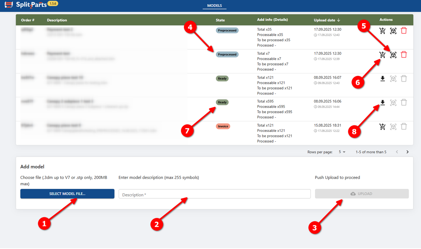
- Select file with your 3D model; model shall fulfill such criteria:
- .step/.stp or .3dm (of Rhino version 7) file format
- File size up to 200 MB
- Up to 700 objects on file
- In public alpha version only plate parts (both flat and bended) without any machining like chamfers, bevels or blind holes can be processed
- Plate parts to be represented by solid or closed polysurface objects, other object types will be ignored
- Please, make sure that model does not contain profiles like circular and rectangular tubes or flat bulbs – they can be recognized as a plate part, however, it will be processed incorrectly
- Add short description of model;
- Press upload button. When uploaded, model automatically proceeds to a preprocessing stage, where it will be validated:
- If model contains more than 700 objects, processing will be terminated automatically
- All objects except of solids and closed polysurfaces will be deleted
- Plates will be recognized, thickness measured (NOTE: at the moment, if profile parts are present in the model, they can be recognized as plate parts. If it is the case, such parts can be manually removed from processing on a later stage)
- Wait until model status is Preprocessed (it can take from 5 minutes to several hours, depending on your model size and complexity)
- When model is preprocessed, 3D view model is available in browser – you can see your model, change part attributes if needed (this step is not strictly required)
- When model is ready for final processing, press Purchase button, perform payment (in public alpha, fixed price for whole package) – when payment is approved, model processing is started automatically
- Model processing can take from half of an hour to 24 hours, depending on model complexity and number of parts. Wait until model status is Ready
- When model status is Ready, Contours package download button will appear instead of Purchase button. Press it, and contours package download will start (Contours package is a .zip archive with .dxf contours, sorted by material and thickness and .stp files for individual parts, also sorted by material and thickness)
3D viewer window layout:
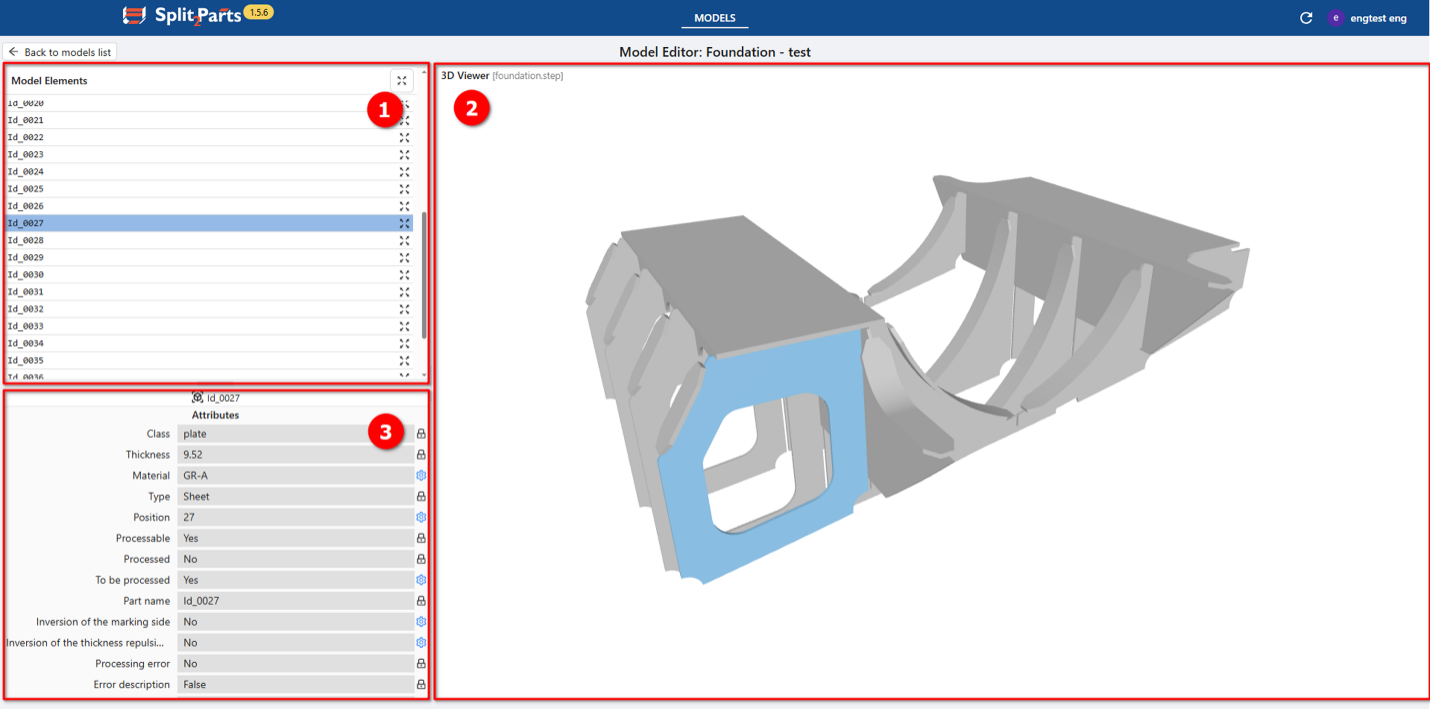
- Model elements list – by clicking on row with certain part, that part will be highlighted in 3D viewer and its attributes will be displayed in Attributes section
- 3D viewer – here your 3D model shall be displayed, cleaned up of obviously invalid objects (non-solids, lines, casted parts etc.). You can rotate? Zoom and pan model, by clicking on certain part it will be highlighted (both in 3D viewer and Model elements list), and its attributes will be displayed in Attributes section
- Attributes section – Here attributes of selected part are displayed. Attributes can be editable (marked with blue gear icon) or read-only (marked with grey lock icon). For detailed description of attributes, see list below.
Part attributes description (most important parameters are highlighted in
blue):
- Class (non-editable) – part category (plate, profile, machined part, casted part…)
- Thickness (non-editable) – thickness if it is plate part (is defined automatically when preprocessed)
- Material (editable) – by default, GR-A is set up, but can be changed manually (as plain text input)
- Type (non-editable) – part type (sheet, L-profile, HP, tube…)
- Position (editable) – position number (will be shown near marking line, left by this part on another part)
- Processable (non-editable) – status of part, defined during preprocessing, showing if this part can be processed by further processing
- Processed (non-editable) - status of part, defined during processing, showing if this part was already processed by processing (in 3D viewer, shall be always No)
- To be processed (editable) - status of part, defined by user, showing if part will be processed. If No, this part will not have contour generated, and will not leave any traces/marking lines on other parts. By default, set to Yes
- Part name (non-editable) – contains Part name, which is combined of system-generated name (ID_XXXX) and object name, read from initial model (if any)
- Inversion of marking side (editable) – if plate part has welded joints with other parts on both sides, marking lines from only one side to be taken and applied to the contour (NOTE: in public alpha contours will be created for both sides of part)
- Inversion of thickness repulsion side (editable) –marking lines on other parts are left by mould side of part. It is defined automatically by preprocessing, but it is possible to invert it (NOTE: in public alpha version it is imposible to preview mould side)
Limitations:
Onlt plate parts can be processed correctly. Plate part - solid or closed polysurface 3D-object, that represents plate part. It can be flat or bended with straight edges (without chamfers, bevels) and structure shall be symmetric relatively to neutral surface (no blind or stepped holes or similar machining). Also, if side of plate part consists of several surfaces, they must be connected tangentially. Only such parts can be correctly processed; parts, which are not complying to these requirements will bne processed incorrectly.